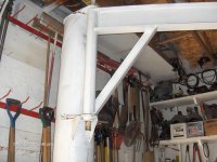
Gantry Hoist

indy_500

Well-known member
I guess you need a shop that nice when you're always spending time wrenching on them cats! HaHa I'm just kiddin, I probably wrench on mine more than most of the guys on here, but most of mine is just useless wrenching, like taking apart stuff to clean it. AND, my sled is still super dirty! I blame it on all the wd-40 i drench on there in the spring for its hibernation.
 

frnash

Active member
Just wait for Professor Nash to chime in. He's got nothing but time to look this kind of stuff up. I think he even enjoys it! :)

Where ya at Nash, still working the figures out, or still checking over the grammar?:D
Sorry, that's completely out of my expertise. I did know a number of Mechanical Engineers in my years at "da Tech", but that's as close as I got to it, no Statics, Dynamics, Kinematics, Strength of Materials, Materials Science, Manufacturing, or Machine Design courses for me. I was instead virtually living in MTU's Digital Computer Lab.

As close as I personally got to "Engineering" was Engineer ROTC Summer Camp (Building Timber Trestle Bridges, Pontoon Bridges, Bailey Bridges; Road construction, Rigging, Explosives & Demolitions (Now that was a really fun course!).

Well perhaps Rigging would be close to this issue, but it was more "field expedient" rigging, using "home made' gin poles, and the like.

As a result, I do have a great deal of respect for skilled, competent Mechanical and Civil Engineers in particular.
 

yamadooed

Active member
Based on all the important information you posted up I wouldn't exceed 1 ton mark.

Now for the weakness I see inherent in design I would change the beam plates to four bolts instead of two and mount gussets on a true 45deg angle to the top beam.

disclaimer: I'm not an engineer as all knowledge posted here is based on 30 years of destructive testing of meticulously engineered products and a pinch of bs...
 

Marty

New member
Try hooking it to the hitch on the truck and measure the beam to ground distance as you put more load on it. Also measure between the legs to see if they are spreading out. Then you will have a good "feel" for how hard you can pull on the chain when the beam starts to flex or the legs try to spread out. Not sure how much flex is ok but those chainfalls can pick up waaaay more than they are rated.
 

jr37

Well-known member
Based on all the important information you posted up I wouldn't exceed 1 ton mark.

Now for the weakness I see inherent in design I would change the beam plates to four bolts instead of two and mount gussets on a true 45deg angle to the top beam.

disclaimer: I'm not an engineer as all knowledge posted here is based on 30 years of destructive testing of meticulously engineered products and a pinch of bs...

Already plan to go to 4 bolts on the beam plates, and the plan was to have the gussets at 45 degree angles. I just missed my mark when welding them, may have to redo some day.
 

cdsprague

New member
Looks nice. Ditch the wheels and anchor it to the cement and you would have no problem getting 2500 lbs. out of 'er. You can look the steel up in a book or on line and it will tell you what 4" I beams will structurally handle. Can't wrap my mind around what you would be looking for at the moment. As in the book name or online... It would ask the size of the beam, span, and it would tell you what it is rated for. Oh and brand of beam. It does make a difference!
 
Last edited:

Skidooski

New member
I'm an engineer. There are several calculations that really should be done; max deflection, column buckling and max shear stress. You can do a simple max deflection calulation at the center and have a general idea of what you could lift. I would not lift any more than what a 1/4" deflection will yield. Here's the formula:

Max deflection @ center = (Load) X (length between supports)cubed divided by (48 X E X I)

E= modulus of elasticity of steel, should be 30,000,000psi
I= moment of inertia in inches to the 4th power. The moment of inertia for an I or wide flange beam will have to come from a structural steel book or probably a web surf. From your picture you would use the value from the X-axis.

Hope the formula is understandable. The gantry looks nice.
 

700classic

New member
:(
I'm an engineer . There are several calculations that really should be done; max deflection, column buckling and max shear stress. You can do a simple max deflection calulation at the center and have a general idea of what you could lift. I would not lift any more than what a 1/4" deflection will yield. Here's the formula:

Max deflection @ center = (Load) X (length between supports)cubed divided by (48 X E X I)

E= modulus of elasticity of steel, should be 30,000,000psi
I= moment of inertia in inches to the 4th power. The moment of inertia for an I or wide flange beam will have to come from a structural steel book or probably a web surf. From your picture you would use the value from the X-axis.

Hope the formula is understandable. The gantry looks nice.
Holy Crap! I was lost after " I'm an engineer":confused:
 

jr37

Well-known member
I'm an engineer. There are several calculations that really should be done; max deflection, column buckling and max shear stress. You can do a simple max deflection calulation at the center and have a general idea of what you could lift. I would not lift any more than what a 1/4" deflection will yield. Here's the formula:

Max deflection @ center = (Load) X (length between supports)cubed divided by (48 X E X I)

E= modulus of elasticity of steel, should be 30,000,000psi
I= moment of inertia in inches to the 4th power. The moment of inertia for an I or wide flange beam will have to come from a structural steel book or probably a web surf. From your picture you would use the value from the X-axis.

Hope the formula is understandable. The gantry looks nice.

Thanks for taking the time to reply, but I haven't got a clue what you are talking about. I'm a truck driver, not an engineer. I do know a little about alot, and alot about nothing. I think I will just try not to overload the thing, and hopefully it will not collapse on me.
 

Skidooski

New member
Thanks for taking the time to reply, but I haven't got a clue what you are talking about. I'm a truck driver, not an engineer. I do know a little about alot, and alot about nothing. I think I will just try not to overload the thing, and hopefully it will not collapse on me.

jr37,
If you want to give me a little info, I would be happy to do the calculations for you. This is what I need:

1. The distance between the upright legs center-to-center, in inches.
2. The size of the top cross beam that the trolley is on. width X depth and thickness of the web, in inches. With those three dimensions I could probably determine the actual beam size form my charts. I-beams or W-beams are usually ordered by, depth (height) and weight per foot.

I would need these two pieces of info.
 

jr37

Well-known member
jr37,
If you want to give me a little info, I would be happy to do the calculations for you. This is what I need:

1. The distance between the upright legs center-to-center, in inches.
2. The size of the top cross beam that the trolley is on. width X depth and thickness of the web, in inches. With those three dimensions I could probably determine the actual beam size form my charts. I-beams or W-beams are usually ordered by, depth (height) and weight per foot.

I would need these two pieces of info.


It is 121" center to center in width. The top I-beam is 2 3/4" x 4", the legs are the same I-beam as the top.

What do you mean by thickness of the web?
 

Skidooski

New member
jr37,
The web of an I-beam is the vertical connection from the top flange to the bottom flange if you are looking at the end of it. From the dimensions you gave me, there are two possible choices of I-beams: S4 X 7.7lb which would have a .193" thick web or a S4 X 9.5lb which would have a .326" thick web. Because I'm not certain which one you have, I used the specifications for a S4 X 7.7lb beam. This is a little lighter duty beam, but will error to the safe side.

From my calculations, 500lbs at the center would yield a deflection of .101".
at 1000lbs this increases linear to .202" of deflection. This is static loading. That just means what ever you lift is just hanging there. Now, if you start wrenching, pulling, yanking on the thing the load goes up, the deflection increases.

There are still a number of things to consider but without being too lengthy, I would not recommend lifting more than 750lbs. The gusset bars from the column to the legs might help reduce deflection but they also put a horizontal load (force) into the legs which could contribute to buckling.

Hope this helped some, but with any lifting structure, please be careful.
 

jonesin

Well-known member
if it is S4x7.7, the Sx=3.04
assuming its old and 36ksi... allowable moment=3.04x.6x36ksi = 65.6ink
Moment=PL divided by 4 therefor P=65.6x4 divided by 121" and P is the allowable load of 2.16kips or 2160# at failure.

thats ignoring deflection as long as we don't care if it bends as long as it doesn't fail
thats also ignoring the braces which should increase the allowable load dramatically

thats assuming that I remembered the formula's right from soooooo long ago, I would trust the other guy more but I wouldn't worry about it much

sure is sweet! good job!
 

favoritos

Well-known member
This is a great thread. The one thing I noticed though on the hoist is that all the I beams are the same. How much could one change the lift capacity by just replacing the top beam and mounting the thing secure?

It's funny that the term Gantry Hoist meant nothing when reading the original post. My folks have one on the farm but we never did call the thing by that name. BTW, it has a very heavy top beam.
 

xcr440

Well-known member
Here's the one my dad built. It is on a swivel inside the garage door. I think he said its 8 feet below the concrete surface, and has a 14' arm. Obviously you don't want to lift very heavy items out on the end of the beam, but it has no issue lifting a sled or ATV out there.
 

Attachments

  • HPIM0906.jpg
    HPIM0906.jpg
    92.9 KB · Views: 32
  • HPIM0907.jpg
    HPIM0907.jpg
    94 KB · Views: 29
  • HPIM0909.jpg
    HPIM0909.jpg
    92.7 KB · Views: 28
Top