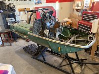
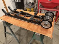
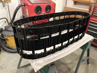
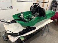
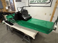
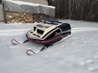
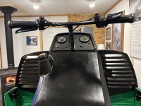
"Continue to be amazed at the engineering that John Deere put into this sled."
Just curious, care to elaborate when compared with your other projects?
Well Gary, you had to ask.
By today’s standards it might not be so impressive but this sled was designed many, many years before auto-CAD and computer modelling became commonplace.
One overall thing that is very evident is that this sled was designed with durability and serviceability in mind. Everything just seems to fit together well and almost all chassis components are bolt-on, with literally every nut on this sled being a locking nut.
It’s hard to pick out specifics because there are so many little things you run across when working on it but here’s a few that come to mind quickly.
The Cyclone used a front crossmember assembly design that was adopted by a number of performance sleds of the day but I really like the Deere design. It attaches to the chassis frame horns with very long connecting surfaces and the fit is very precise. Unlike some that used rivets or welds to attach the assembly, this sled utilizes bolts, which allows for easy removal or installation.
This sled also used a steering design that was a departure from the standard twin tie-rod design that was popular back in the day. Instead, it used a single steering rod that connects to one ski spindle steering arm and a cross link to connect the two spindle steering arms. Polaris also used a similar design in their later model TX’s but it’s my opinion that the Deere design was better in one aspect: The link connects the spindle arms from behind the spindles rather than in front. This allows for a shorter link rod and makes it less likely to bend, which was a common problem on the TXs.
On the rear suspension, a couple of things jump out: First the pivot shafts run through nylon, replaceable bushings, which require little or no lubrication and don’t seize, which is common for the designs that run aluminum shafts through steel tubes. Second, the suspension can be installed before tensioning the springs so it is not under load when trying to line up the mounting holes. When the springs are tensioned, they are connected to the chassis by a tensioning arm that uses a threaded bolt for adjustment. The tension on all four springs can be adjusted individually using just a socket and ratchet.
My apologies for a long answer to a short question. Maybe I spend a little too much time thinking about this stuff when I’m out in the shop.

